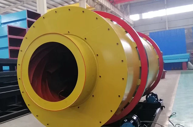


Metallurgical Rotary Kiln Shell Structure Design: How to Ensure Strength and Stability
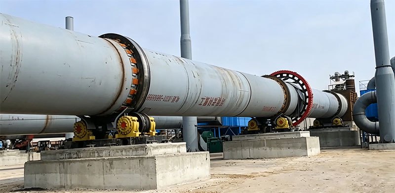
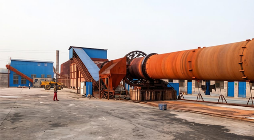
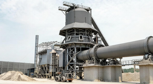
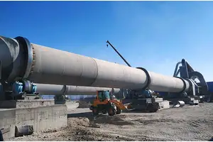
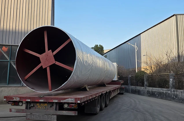
The shell of a metallurgical rotary kiln is the most fundamental and critical load-bearing structure of the entire equipment. It must simultaneously withstand self-weight, refractory material weight, material weight, and complex stresses from support roller compression under high-temperature, heavy-load, and continuous rotation conditions. Once the shell undergoes excessive deformation or cracking, it can range from loose or falling refractory bricks in mild cases to major accidents such as tire fracture or support roller shaft breakage in severe cases. Therefore, the core objective of shell structure design can be summarized in one sentence: ensure "rigid transversely, flexible longitudinally"—sufficient rigidity in the cross-section to resist radial deformation, and appropriate flexibility in the longitudinal direction to absorb additional stresses.
I. Core Design Principle: The Mechanical Logic of "Rigid Transversely, Flexible Longitudinally"
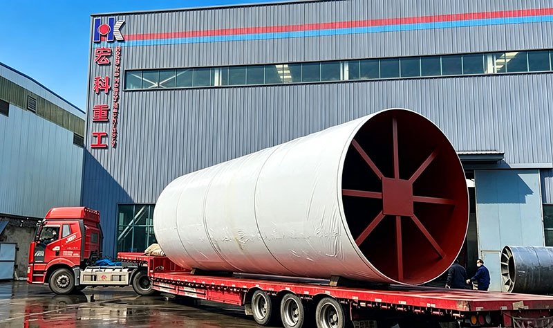
"Rigid transversely, flexible longitudinally" is the basic principle of rotary kiln shell design, aimed at improving operation rate and reducing raw material consumption. The mechanical basis for this principle comes from the stress characteristics of the shell during operation: the shell generates axial bending between two support roller stations and produces relatively large radial deformation at the tire positions.
If the shell's transverse rigidity is insufficient, the radial deformation (i.e., ovality) at the tire positions increases significantly. Excessive radial deformation compresses the internal refractory bricks, causing the lining to loosen, crack, or even fall off. If the shell is too rigid longitudinally, it cannot compensate for additional loads caused by uneven foundation settlement, support roller installation deviations, or thermal expansion differences through its own slight bending, instead accelerating localized stress concentration.
Therefore, the essence of the design is trading thickness for rigidity and span for flexibility—using thick steel plates under the tires to enhance local stiffness, while appropriately increasing support spans to utilize longitudinal flexibility to equalize loads.
II. Determining Shell Thickness: Thick at Critical Points, Thin in Non-Load-Bearing Zones
The shell is not uniformly thick throughout but is designed differentially according to the stress characteristics of each part. Steel plate thickness increases with kiln diameter, using thicker plates at positions with greater stress such as under the tires (at support rollers) and the kiln head section.
Taking typical data as an example: for a kiln with a diameter of 4 m, the shell plate thickness between spans and under the tire is 30 mm and 65 mm respectively; for a kiln with a diameter of 5 m, the plate thickness between spans and under the tire is 45 mm and 100 mm respectively. This differentiated design ensures the ability to resist radial deformation at the tire positions while avoiding material waste and loss of longitudinal flexibility caused by excessive thickening between spans.
At the tire positions, in addition to using thick steel plates, dozens of evenly distributed backing plates are installed around the shell circumference, making the shell stress more uniform, preventing the shell from being worn by the tire, and providing better heat dissipation conditions for the shell. The tire itself, as a sturdy large steel ring, not only transmits all gravity to the support rollers but also serves to increase shell rigidity.
III. Reasonable Configuration of Support Spans and Cantilever Lengths
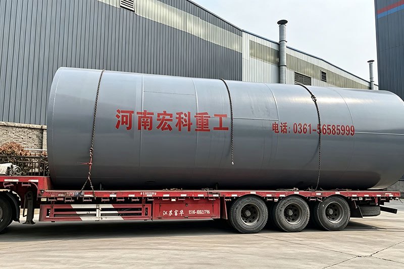
The configuration of the number of supports and spans directly determines the longitudinal bending stress and deflection of the shell. The design trend for large kilns is to reduce the number of support stations and increase support spans, based on the principle that the main hazard to material life comes from radial deformation of the shell, while the longitudinal flexibility brought by large spans helps reduce uneven loads caused by kiln misalignment or improper support roller installation.
In determining spans, a key constraint must be satisfied: the maximum deflection of the shell between two support points should not exceed 0.0003L (L is the shell length), while controlling the length-to-diameter ratio L/D to less than 8-9. For cantilever ends, the feed end cantilever length L_h should be as large as possible to reduce the bending moment of the intermediate shell, but should not exceed 3.3D; the discharge end cantilever length L_t should be less than L_h, generally controlled within 3D, to avoid insufficient burning zone length affecting the material's completion of phase transformation.
IV. Precision Control of Welded Structure and Shell Section Assembly
The shell is welded from multiple steel plates of different thicknesses, and welding quality directly determines the overall strength of the shell. In structural design, the following key rules must be followed:
Weld seam arrangement: Longitudinal welds of adjacent shell sections must be staggered by more than 45°, with butt welds arranged in a crossing pattern to avoid weld seams concentrating on the same generatrix. Circumferential welds must not pass through discharge holes, manholes, and other openings, and the distance between holes and welds must not be less than 100 mm.
Shell section length: The width of ordinary sections should be between 1.8-2.5 m; small sections such as high-temperature sections, low-temperature sections, and gear sections should generally not be less than 1 m; within the same span, there should not be more than one shell section with a width less than 1.5 m, and it should be arranged in the middle of that span.
Welding process: Shell welding typically uses submerged arc welding, and welds must undergo ultrasonic flaw detection, meeting the Level II requirements of relevant standards. Weld reinforcement in general areas inside the shell should be ≤1.5 mm, and in the burning zone and adjacent areas (within a length range of 9 times the shell inner diameter from the discharge end) should be ≤0.5 mm.
V. Material Selection and Manufacturing Precision Assurance
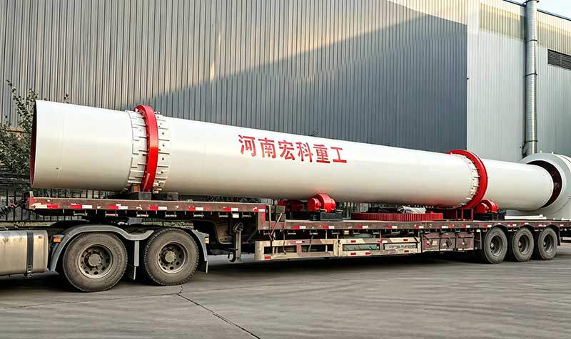
The selection of shell materials is related to kiln diameter: for kilns with diameter D≤4 m, the material should be no lower than Q235B; for kilns with diameter D>4 m, the material should be no lower than Q235C. For metallurgical rotary kilns with special heat resistance requirements, boiler carbon steel or heat-resistant stainless steel may be used.
The manufacturing precision of the shell directly affects strength. After welding is completed, the straightness of the shell axis and the roundness of the cross-section must be ensured. During installation, a theodolite is used to measure the horizontal tolerance of the four support roller wheels at ≤0.2 mm, and a tape measure is used to measure the diagonal deviation of the quadrilateral formed by the centers of the four wheels at ≤1 mm. During shell assembly, longitudinal welds of adjacent shell sections are staggered by more than 45°, and gapless butt jointing ensures that the misalignment is uniformly达到 design requirements.
VI. From "Design" to "Operation": Continuous Assurance of Strength and Stability
The strength and stability of the shell cannot be permanently guaranteed by a one-time design. Even if installation is very accurate, after a period of operation, uneven foundation settlement, support roller bearing wear, inner and outer ring wear of the riding ring, and significant temperature changes at various locations may all cause the center position of the shell at each support point to change. Therefore, the axis must be inspected and corrected according to the kiln's operating conditions.
In daily operation and maintenance, shell ovality detection is an important means of judging shell rigidity and the fit of internal refractory bricks. By measuring shell ovality in real time, the rigidity of the shell and the fit of internal refractory bricks can be judged, and abnormalities in the ovality curve can also reflect overall problems in the rotary kiln. The phenomenon of abnormal damage to refractory bricks in the tire area caused by mechanical stress generated by shell deformation can often be predicted in advance through correlation analysis between ovality detection data and refractory brick damage at tire positions.
Henan Hongke Heavy Industry's mineral processing equipment enjoys significant competitive advantages in the industry. We provide one-stop full-chain services covering pre-sales consultation, in-process follow-up, and after-sales support, ensuring every customer buys with confidence and uses with peace of mind. Click Customer Service Consultation to leave us a message. You are welcome to visit Henan Hongke for on-site inspection and business negotiation. We will provide you with professional solutions and quotations!